
Definition of finite element simulations
Finite element simulations are a powerful method for studying and analyzing physical phenomena and engineering problems. This simulation method is based on the concept of dividing a complex system into smaller, more manageable elements. Each element is then analyzed individually and the results are brought together to gain a comprehensive understanding of the entire system.
By applying finite element simulation, engineers and scientists can test various scenarios, predict the effects of design changes, and evaluate the performance of structures or devices under various conditions. This simulation method is used in various fields such as construction, automotive engineering, aerospace, medicine and many others.
This section explains the basics of finite element simulations to provide a better understanding of this important technique. From the definition and key principles to the applications and benefits, this section will provide an overview of the world of finite element simulations.
Importance of numerical methods in technology
Numerical methods play a crucial role in engineering because they can efficiently solve complex mathematical models and problems in practice. They are used in various engineering disciplines such as mechanical engineering, aerospace engineering, electrical engineering and chemical engineering to model, simulate and analyze complex problems.
These methods offer the advantage of being able to solve complex mathematical equations and models quickly and accurately, saving time and costs when developing new products or optimizing processes.
The finite element method is one of the most commonly used numerical methods in engineering. It enables the analysis of complex structures and material behavior under different loads. Their specific functions include modeling stresses, deformations, heat transfer and fluid flows. Examples of their application in various technical areas include the analysis of components in aerospace, the simulation of flow processes in the automotive industry and the optimization of building designs in the construction industry. By applying the finite element method, engineers and technicians can improve the performance and reliability of products and processes.
Understanding finite elements
The finite element method is a numerical method that was developed in the 1950s and was originally used to calculate the structure of aircraft wings. However, it has evolved and is now used in various areas, including the study of solids of complex shape and as a numerical method for solving differential equations.
The importance of the finite element method lies in its ability to model complex geometric structures with high accuracy and to study the physical properties of these structures. By refining the elements, the accuracy of the calculations can be further improved, making it possible to make accurate predictions about the behavior of materials and structures.
The finite element method has become an important tool over the years in various fields, including engineering, materials science, biomechanics and geosciences. The continuous development and application of this method has helped to improve the efficiency and accuracy of simulations and analyzes in these areas.
Overview of Finite Elements
The finite element method is a numerical technique for solving differential equations found in many engineering and physics problems. It enables the approximation of complex structures by breaking them down into smaller, simpler regions, which are referred to as "finite elements". Each of these elements is then described mathematically and connected together to simulate the behavior of the entire system.
The CAD geometry is broken down into these finite parts to perform a more detailed analysis. This process of networking makes it possible to take into account the complexity of reality and make the results more precise.
In order to apply the finite element method, the computing machine needs information about the material properties, the boundary conditions of the system and the geometry of the object to be analyzed. Based on these inputs, the computing machine can then perform the calculations and deliver the results.
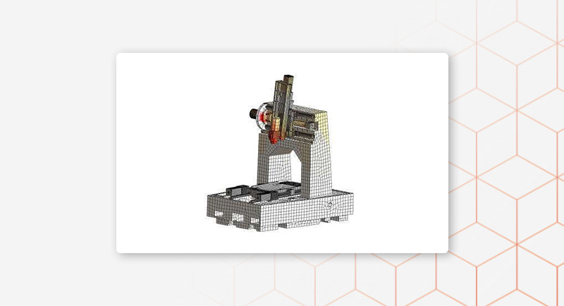
Division of complex components into individual elements
The specified CAD geometry is used to divide complex components into individual elements. Subdivision is done by breaking the 3D model of the component into smaller elements that can be used for modeling and analysis. When chopping geometry, it is important to pay attention to the structure and shape of the elements to ensure that the computational mesh can be created correctly.
When networking, the individual elements are connected to each other to create a computing network. This process is important because the computing network forms the basis for the calculations and analyzes of the component. When networking, the different elements must be connected to each other in such a way that an accurate and reliable analysis is possible.
It is important to pay attention to the quality of the elements when chopping the geometry to ensure that the computational mesh can be created correctly. Elements such as tetrahedrons, hexahedrons or prisms should be used, depending on the requirements of the component and the analysis. By carefully dividing and networking CAD geometry, complex components can be broken down into individual elements to enable precise analysis and modeling.
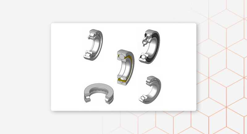
Behavior of complex components with simpler elements
The behavior of complex components can be modeled using simpler elements to perform finite element analysis (FEM). This means that the complex component is broken down into smaller, simpler elements in order to understand the behavior of the entire component. These simple elements can be lines, triangles or squares, for example.
To model and analyze complex components with simple elements, the following steps are required: First, the component is divided into smaller elements and then the connections and boundary conditions between the elements are defined. The material and load data are then determined and the FEM analysis is carried out.
The advantages of such an approach lie in the possibility of precisely analyzing the behavior of complex components without having to carry out complex and costly physical tests. In addition, weight reduction can be achieved with increased component strength because material distribution and utilization can be optimized through FEM analysis. This contributes to the development of lighter yet high-performance components and leads to cost savings and efficiency improvements in various industries.
The finite element method
The finite element method (FEM) is a numerical method for approximating solutions to partial differential equations. It has found wide application in engineering and other technical fields in recent decades. The method is based on breaking down the area under study into smaller, simpler parts called finite elements. These elements are then used to transform the differential equations into a series of algebraic equations, which can then be solved numerically.
The finite element method provides a flexible and efficient way to model and analyze complex problems that arise in the real world. It allows the consideration of materials with nonlinear behavior, complicated geometries and boundary conditions that occur in many applications. In addition, FEM can also be used to investigate thermal, electrical and fluid mechanical phenomena.
The following headings highlight various aspects and applications of the finite element method to illustrate its importance and versatility in various disciplines.
Solve physics problems using numerical approximation methods
The use of numerical approximation methods, particularly the finite element method (FEM), is an important approach to solving physical problems in construction and materials science. By using FEM, complex components can be analyzed and optimized, resulting in improved component optimization, reliability and weight savings. FEM analyzes make it possible to calculate the loads and stresses in a component under different conditions, thereby identifying potential weak points and optimizing the design.
Schunk Technical Ceramics offers additional services in the area of FEM analyzes to optimize the reliability and weight savings of components. Virtual testing can reduce development times and costs by minimizing complex and expensive physical testing. This enables more efficient product development and optimization.
Advantages of finite element simulations
Finite element simulation (FEM) is a powerful method for numerically solving complex engineering problems. By using FEA, engineers and scientists can achieve a variety of benefits, allowing them to develop precise and efficient solutions. This article explores the various benefits of finite element simulations and how they can be used in various industries such as mechanical engineering, aerospace, construction, and biomechanics. From reducing development time and costs to improving product designs and predicting the behavior of materials under different loads, FEM offers a wide range of possibilities that are invaluable to engineers.
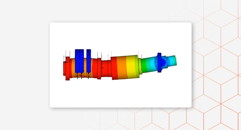
Accurate results compared to analytical solutions
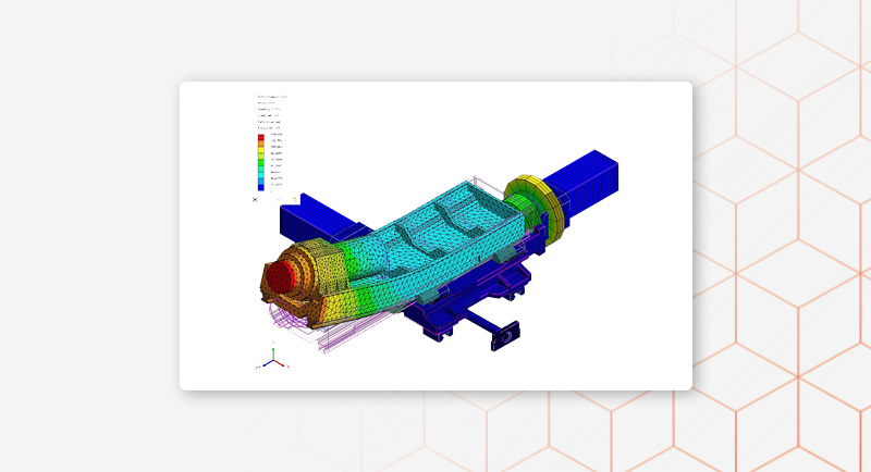
The FEM calculation provides accurate results compared to analytical solutions. By simulating the behavior of complex individual parts, FEM simulation clearly visualizes the stress distribution and deformations, which are often difficult to visualize in the analytical solution. The results can be interpreted by looking at the stresses, deformations and load distributions and comparing them with the specifications and requirements.
The differences between the FEM results and the analytical solutions may occur in some cases, mainly due to assumptions in the analytical solution that only apply to simple geometries and load cases. The FEM calculation, on the other hand, takes into account the actual geometry and material behavior as well as complex load cases and boundary conditions. Similarities between the FEM results and the analytical solutions lie in the accuracy when the FEM calculation is well validated and compared with real test results.
Possibility of calculating component behavior under external loads
The Finite Element Method (FEM) and the Computational Fluid Dynamics (CFD) method are two established techniques for calculating component behavior under external loads. With FEM, the component is divided into small elements in order to calculate the local stresses and deformations. The CFD method, on the other hand, is used to analyze the flow behavior of fluids around the component.
These methods are used to analyze the behavior of components under dynamic loads by taking into account the time-dependent effects of loads and deformations. Similarly, fatigue life considerations can be performed to determine fatigue and material failure over time.
For tasks in which both flow and structure play a role, different approaches can be pursued, such as the coupling of FEM and CFD methods, the simultaneous solution of flow and structural equations (FSI), or the use of multiphysics approaches , to take into account the interactions between flow and structure. These approaches enable a comprehensive analysis of component behavior under complex conditions.
Inclusion of physical laws and equations in simulations
Incorporating physical laws and equations into simulations is crucial for accurately predicting the behavior of materials and structures under various loading and environmental conditions. The finite element method (FEM) enables the calculation of complex thermal simulations by converting the physical laws such as heat conduction and heat transfer into equations.
Considering linear and non-linear material behavior is important to achieve realistic results and simulate the actual behavior of materials under load. It is also very important to consider different contact situations in order to correctly record interactions between different components or materials.
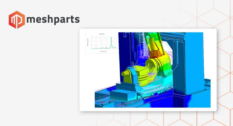
Various types of analysis, including stress analysis, structural analysis and temperature analysis, should be included in the simulation to take into account all relevant physical laws. Modal analysis, for determining the natural frequencies and mode shapes, as well as determining the propagation of vibrations in the component, also plays an important role in incorporating physical laws into simulations.
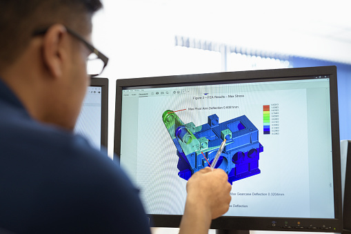
Better understanding of complex components
FEM analysis makes it possible to analyze complex components through different steps. First, the model is prepared by breaking the component down into individual elements. The material properties, boundary conditions and loads are then defined to determine the parameters for the calculation.
The FEM software then solves the equations that describe the physical behaviors of the component using numerical methods such as the finite element method. Complex differential equations are solved to calculate the stresses, deformations and other physical quantities in the component.
In post-processing, the results of the calculation are displayed and analyzed. Visualizations, such as coloring of stress states, deformation diagrams or comparisons with limit values, can be created to understand the behavior of the component under different conditions.
Gaining insights into the behavior of complex systems
Finite element method (FEM) is used to gain insights into the behavior of complex systems using mathematical models and simulations. In various analysis areas such as stiffness and strength analysis, thermal simulation and modal analysis, FEM simulation enables the accurate prediction of the behavior of structures and materials under various loads.
The advantages of FEM simulation lie in the time and cost savings in the product development process. By virtually analyzing components and structures, potential problems can be identified and resolved early, avoiding expensive prototypes and testing. In addition, FEM simulation enables the optimization of materials and functionality, resulting in improved performance and reliability of products.
The most important areas of application for FEM simulations include the automotive industry, aerospace, mechanical engineering, construction and medical technology. Examples of practical applications include the strength analysis of vehicle components, the thermal simulation of electronic components and the modal analysis of structures for vibration analysis. FEM simulation therefore plays a crucial role in the development and optimization of modern technologies and products.