
Today I'll tell you how Finite Element Analysis (FEA) has developed over time. Above all, I want to highlight why (the vast majority) of FEA programs work the way they do today. And finally, I would like to explain why I think a change in thinking for users is a good idea.
Computer Aided Design (CAD)
The FEA was tied to the development of the CAD systems almost from the beginning. Therefore, it is first important to look at the development of CAD.
In the early days, CAD programs were simple 2D sketching tools, without any special intelligence.
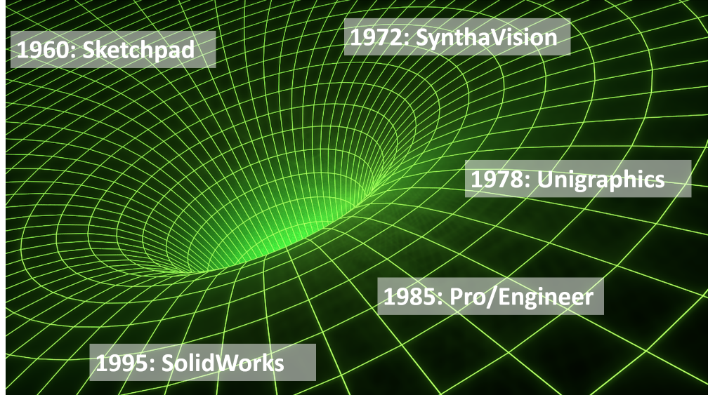
1960 Ivan Sutherland developed the first modern 2D CAD program as part of his doctoral thesis: SKETCHPAD. For the times, the new program was a revolution. SKETCHPAD's two key groundbreaking unique selling points were:
- The automatic solving of complex geometric constraints (e.g. perpendicular, parallel, collinear, equal length, etc.)
- Object-oriented approach (individual drawings could be reused and assembled to create larger drawings)
The following video demonstrates the impressive way SKETCHPAD works: Watch video
It took 12 more years until the first 3D CAD program was released 1972 pass:SynthaVision. The next video shows some animations created with SynthaVision. However, 3D CAD programs were too resource-intensive for computers at the time. For this reason, mass distribution could not yet take place. Watch video
1978 was with the publication of Unigraphics set a new standard in 3D CAD modeling: Watch video
1985 is Pro/Engineer published by the company PTC. Despite initial teething problems, a real revolution! Pro/Engineer immediately overshadowed all previous systems. By the way: Pro/Engineer was the first 3D CAD program that consistently implemented the concepts of SKETCHPAD(!) into the 2D and 3D world. Here is a demo video of the software version at the time: Watch video
10 years later –1995 - is SolidWorks appeared. It offered most of the functionality of existing leading CAD programs, but cost only a fraction of them. Here is a demo from 1995: Watch video
The success of SolidWorks was so great that the small company was bought by Dassault Systemes two years later. Finally, a demo video from SolidWorks from 2007 that focuses on assembly modeling: Watch video
If you've watched the old software demo videos above, you've probably already recognized the milestones of CAD development:
- First: 2D sketches
- then: 3D individual parts
- much later: 3D assemblies
But I would also like to draw your attention to something else: The concept of assemblies was already known in 1960 (at the latest through SKETCHPAD). Despite the obvious advantages of assembly modeling, 3D CAD first focused on modeling individual parts! It was only 25 years after SKETCHPAD that the concepts of that time were taken up and implemented into a 3D CAD program. That was also one of the main reasons why Pro/Engineer became so successful.
Finite Element Analyse (FEA)
Now that we have an overview of CAD development, I would like to turn my attention to FEA development.
The basis of FEA is the FEM (Finite Element Method), which has its origins in the 1940s. The first commercial FEA software was 1971 presented to the public: NASTRAN.
Originally, the available computer power was only sufficient for rough calculations of individual parts.
Large assemblies are less and less a problem for today's computers. At least that's what all manufacturers of FEA software claim. For some this is true, for some others it may only be half true. When talking to engineers from different mechanical engineering companies, I often hear that larger CAD assemblies are first merged into individual parts before they are imported into the FEA environment. I then ask why, and the answers are often: Too many individual parts lead to many contacts, too many contacts can no longer be checked for accuracy. Or that the FEA software cannot properly close the larger gaps between the individual components. Or that purchased parts such as rolling bearings, linear guides and ball screws can only be oversimplified or not modeled at all. These are just a few reasons and we recognize that when it comes to assemblies and FEA, the devil is in the details.
It almost looks as if the major FEA manufacturers want to concentrate on parallelizing the solvers and pay less attention to the many little “devils”. They focus on solving more and more millions of model degrees of freedom even faster (which is generally good for assemblies), but neglect the hundreds or even thousands of - in themselves small - individual components in the usual CAD assemblies.
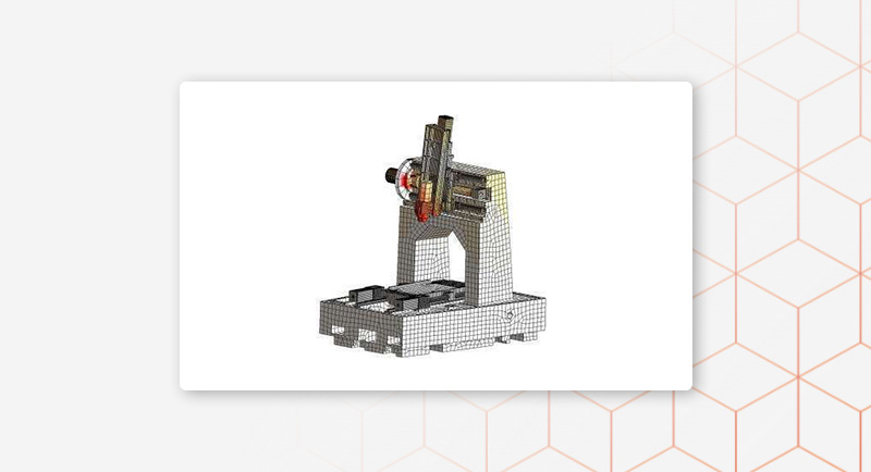
When I started with FEA 20 years ago, I immediately had to deal with entire machines in simulation. It was a jump in the deep end, but it was fun. My first FE simulation was a lithography machine (making TFT screens). Then followed laser cutting machines, milling and lathe machines, etc.
Despite my enjoyment of the simulation, I soon began to feel dissatisfied due to the many repetitive work steps. Design changes to individual CAD components led to a disproportionate effort to make changes to the FE assembly. If a new machine had to be simulated, I had to start from scratch, even though perhaps 50% of the new machine was the same as the old machine. This way of working is still the current state of the art today.
Why is that?
Well, amazingly, the idea of the assembly stops completely with the FEA systems. If a CAD assembly is read into a normal FE program, the assembly structure is first resolved. You end up with a bunch of individual components, without any order, structure or relationship to each other.
Next, the usual FE contacts (the connections between the individual components) are automatically defined. This results in another pile of hundreds, even thousands of contacts. The user should then check these countless contacts for accuracy. Because not every automatically defined contact is a real contact. This is where the fun ends.
The whole thing probably grew historically. Before 1985, the idea of assemblies was not present in the CAD solutions of the time anyway. This is probably why the FEA developers designed their FE programs without the assembly in mind. It is certainly also true that in the past computer resources were limited and therefore only simple models with a few components could be calculated anyway. I have another possible explanation for this: FE simulation of assemblies only became possible with the development of composite contacts. At that point, most of today's FEA programs had already been developed.
Meshparts
And now back to my initial experiences in the FEA. About 15 years ago I realized that all of these problems could be solved by consistently transferring the assembly concept into the FE world. That's the idea of Meshparts was born. At that time I was about to graduate and decided to develop the idea at a research institute at the University of Stuttgart (ISW). Five years later I founded Meshparts. The result is a new type of FEA software - Meshparts, which does so many things differently than all other current FEA programs that it requires access to the historical arc of CAD and FEA development in order to properly understand how it works.
Meshparts was initially a simple configuration tool with which you could automatically combine various individual FE models into FE assemblies. There was also an option to instantiate the same FE model multiple times. And you could move the positions of the components in relation to each other as desired. The whole thing was created at the end of my studies. I then further developed the tool as part of my research work at the institute.
At the same time as developing the tool, I researched how the usual purchased parts in mechanical engineering can be modeled efficiently and reproducibly. I also had the idea that all of these purchased parts could be organized in an FE model library. The same idea has been standard in the CAD world for decades (Traceparts, CADENAS and Co.)
After my time at the research institute and during the first years of Meshparts, I was able to win a few customers and generate sales with the tool that had already been developed. That was all well and good and this tool saved the users back then a lot of work.
Beginning 2014 I decided to turn the tool into real FEA software. The new development took a year until the first release. Just like Pro/Engineer back then, the new mesh parts also suffered from many teething problems. The reason: We had to rethink and redevelop almost everything. To understand a little why Meshparts is so much different, a first note: The FE model of an assembly in Meshparts is a file that is only a few kilobytes in size. The same FE model in the other known FE programs would be at least an order of magnitude larger.
The assembly idea
Meshparts models are real assemblies. This means that the models do not contain information about their individual parts, but only a reference to the individual parts. Only the individual parts contain the actual FE meshes (which require a lot of memory).
But now the first important property of Meshparts: If a CAD assembly is imported into Meshparts, then as many Meshparts subassemblies are created as CAD subassemblies. And as many Meshparts parts are created as CAD parts. Finally, all Meshparts assemblies contain the same assembly structure as their corresponding CAD assemblies. That's why we call the result of a CAD import into Meshparts: "CAD twin".
The library idea
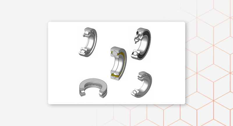
The second important feature of Meshparts is the integrated online library. You can imagine this being similar to CADENAS, but for FEA. So no purchased parts are modeled in Meshparts. Instead, the corresponding CAD models are replaced by existing FE models.
We quickly realized that eliminating the modeling of purchased parts brings with it huge advantages, some of which I would like to mention here:
- The user no longer needs to be an FEA expert to be able to model the complex mechanical behavior of purchased parts.
- Since the same purchased parts are always used in different models, the user saves twice, no, many times, time.
- The reproducibility of the FE results is assured; A significant source of deviations, and sometimes errors, is closed because, as is well known, simulation engineers tend to model their models in one way and another.
The FE model library makes work a lot easier and, almost more importantly, a real gain in quality.
Part Mappings
However, we soon realized that replacing purchased parts is, in principle, a tedious, repetitive job. A solution had to be found.
Not in 2020 do we have the "Part Mappings" introduced. You have to think of it like a table with two columns. In the left column there are names of purchased parts (as well as the CAD file names). The paths to the FE models from the Meshparts library are in the right column. This table can be created at the beginning for all parts or expanded automatically with each new manual replacement. So Meshparts remembers your actions for later. So if a new CAD assembly is imported, the purchased CAD parts no longer have to be networked again; they are automatically replaced according to the part mappings.
The part mappings were a logical extension of the library idea. This gives the user another significant boost in efficiency. But we weren't satisfied with that either. The remaining components and assemblies were next. In order to understand why we were missing something in our software, I have to briefly explain how companies work with PDM systems.
If a CAD designer wants to open a CAD assembly in his CAD program, this assembly is first downloaded from the PDM system and saved locally. Now it could be that the designer wants to change the design of a certain component. He does this with the functions available in the CAD program. When he is finished, he uploads the changed assembly or component back into the PDM system. The changed component is assigned a version number. Every part and assembly in the PDM system has a version number. The file names, however, remain the same. So when a CAD assembly is downloaded from the PDM system, you can tell whether it is an old or new design version based on more than just the file names.
Meshparts, on the other hand, tries to reuse already imported models with every new CAD import. Until recently this only worked based on the file paths and the file modification date. If an imported part did not already exist in the import folder, then this part was created and networked. However, if the part already existed in the import folder, the change date of the FE part was compared with the change date of the CAD part. This allowed Meshparts to decide whether the finished part should simply be adopted directly or whether it should be re-networked because the corresponding part has changed.
Now we had identified three problems with the logic described:
- Because the designer repeatedly downloads the CAD assemblies from the PDM system, the modification date of the CAD files was always different, even if they did not actually change.
- In addition, the folder could still change even though the assemblies contained common parts. Copies of the same files were created in different folders.
- And finally, even components with the same name can still contain different construction statuses.
Due to the three problems mentioned above, until recently Meshparts was only able to reuse purchased parts at best, but not specially designed components or assemblies. Even though it would have been technically possible. The fact is that working with a PDM system has its own peculiarities.
Collection Directories
The solution came End of 2020 in the form of “collection directories” or “collection folders”.
Also the Collection Directories can be thought of as a table with two columns. On the left are the source directories, on the right are the target directories, i.e. collective folders.
When a CAD assembly is imported into Meshparts, all files located under a source directory are copied to the target directory. However, if files with the same name are already in the target directory, they will be taken over from there. This solves the first and second problems (see the list above).
Now the file modification date is no longer checked when using collection directories. This means that existing models are reused regardless of the modification date.
Finally, the third problem from the list above had to be solved. For this purpose, we have developed a simple connection to the PDM system, which is used to check the versioning of the imported files. The version name is adopted and a directory with the same name is created for each versioned component in the collection directory. The corresponding Meshparts models are then automatically stored in these version directories. This means that the PDM connection and the version number replace the file modification date. Otherwise everything stays the same.
Final word
Right from the start, when developing Meshparts, we were guided by one overarching goal, namely to achieve maximum efficiency through consistent automation and reusability.
I am sure that our goal would not be possible if our software were not assembly-based. It's nice for us to see how one optimization leads to the next and how in the end everything makes even more sense.
Finally, I come back to the thought I expressed at the beginning: I think a rethink by FEA users would be a good idea. Ask yourself why your FEA software doesn't know about assemblies. Imagine how different your work would be if you worked with FE assemblies.